
Deciphering Construction Drawing Symbols


Last Updated Aug 14, 2024
Daniel Kavanagh
Solution Specialist, Industry Compliance
15 articles
Daniel Kavanagh is a Senior Strategic Product Consultant at Procore, based in Dublin, Ireland. Daniel is a results-oriented project manager with a passion for building relationships and exceeding client and management expectations, with career experience in project management, systems implementation, technical design and architectural finishes. Daniel has been a member of the construction industry since 2014, and graduated from the Carlow Institute of technology.
Taylor Riso
Contributing Writer
95 articles
Taylor Riso is a marketing professional with more than 10 years of experience in the construction industry. Skilled in content development and marketing strategies, she leverages her diverse experience to help professionals in the built environment. She currently resides in Portland, Oregon.
In construction, every blueprint and drawing is a complex web of information, distilled into symbols and lines that determine the work executed onsite. For those in the field, understanding these symbols is not just a technical skill — it's an essential part of transforming the design on paper into a physical structure. Construction drawing symbols serve as the common language that architects, engineers and builders rely on to ensure every aspect of the project aligns with the original vision.
This article aims to clarify the role and importance of construction drawing symbols in the construction industry. By examining the standardized symbols used across various construction documents, we'll dive into how these notations facilitate effective communication and precision in the building process, ensuring that every detail of the architectural plan is executed correctly.
Table of contents
The Importance of Construction Drawing Symbols
Construction drawings act as a blueprint that guides every phase of construction from groundbreak through closeout, and the symbols depicted on these drawings are the essential language through which detailed construction plans are communicated. Here are some key reasons why construction drawing symbols hold such importance.
Ensuring Accuracy
Construction drawing symbols provide precise details about every component of a project, from the type of materials used to the exact placement of structural elements. This accuracy is vital for preventing costly mistakes and ensuring that the end product aligns perfectly with the planned design.
Facilitating Communication
These symbols serve as a universal language understood by architects, engineers, builders and contractors. They ensure that all parties involved in a construction project have a common understanding, thereby facilitating effective communication and coordination.
Streamlining Approval Processes
The use of standardized symbols helps demonstrate compliance with building codes and regulations, making it easier to obtain necessary permits and approvals from Authorities Having Jurisdiction (AHJs). This standardization ensures that plans are reviewed and approved more efficiently.
Aiding in Budget and Schedule Management
By providing a detailed breakdown of the entire construction process, symbols help in developing accurate cost estimates and scheduling. Contractors can use these symbols to determine material quantities and labor requirements, essential for maintaining budget control and meeting project deadlines.
Enhancing Quality Control
During construction, these symbols act as quality control reference points, ensuring that each element is built according to specified standards. This level of detail is crucial for maintaining quality throughout the construction process.
Serving as a Reference for Future Work
Post-construction, the symbols in the as-built drawings provide a valuable record for any future maintenance, renovations or expansions. They offer insight into the building's original specifications, simplifying any subsequent modifications.
Construction Drawing Symbols as Universal Language on Jobsites
Construction drawing symbols serve as a universal language that bridges the gap between diverse professionals in the industry, including subcontractors, general contractors, architects or engineers. This universal language, underpinned by the standards set by the International Organization for Standardization (ISO), ensures that construction drawings are understood globally, regardless of the project's location or the language spoken by the workforce.
Universal Understanding
Construction drawing symbols provide a standardized way of communicating detailed and complex information across the industry. This standardization means that an architect in one country can create a set of drawings that a builder in another country can interpret without the need for extensive verbal explanations or translations. It transcends language barriers, making collaboration more streamlined and efficient.
The Role of ISO Standards
The ISO plays a crucial role in this standardization process. As a worldwide federation of national standards bodies, the ISO develops and publishes international standards, including those for construction drawing symbols.
These standards ensure consistency and clarity in the interpretation of construction documentation. By adhering to ISO standards, professionals in the construction industry can ensure that their drawings convey the intended message accurately and are in compliance with global best practices.
Facilitating Collaboration
Standardized drawing symbols are indispensable in an industry increasingly characterized by international partnerships and multicultural workforces. This common visual language ensures that all stakeholders, from architects to builders, share an understanding, significantly reducing the potential for costly errors and misunderstandings.
Construction drawing symbols ensure that construction documents are clear, concise and universally interpretable, facilitating global collaboration and contributing to the efficiency and success of construction projects. The standardization of these symbols by the ISO upholds uniformity and clarity within the industry, ensuring that the symbols maintain their intended meaning and function universally.
Common Symbols in Construction Drawings and What They Mean
Construction drawings use a variety of symbols to represent different elements and systems within a building. These symbols provide essential information about the materials, processes and installations involved to turn the plans into reality. Here's a look at some common symbols across various categories and their meanings.
Architectural Symbols
Architectural drawings include symbols for various building elements to convey their design and placement within the structure.
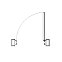 | Doors: Doors are typically represented by a straight line (indicating the side of the door) and an arc (which shows the door swing direction). Different symbols may denote various types of doors, such as double doors, sliding doors, or revolving doors. |
 | Windows: Windows are often illustrated as a pair of parallel lines (the window thickness) with a break or a series of breaks (representing the actual pane). Specific symbols may be used to indicate different window styles, like casement, double-hung or bay windows. |
 | Walls: Wall symbols vary depending on the type of wall represented, with different line weights and patterns indicating structural walls, partition walls or fire-rated walls. |
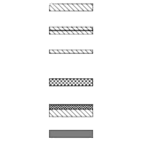
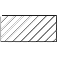
Representing Different Material Types through Hatch Patterns
Hatch patterns are used to indicate the type of material in a section view. Different patterns represent different materials, providing a quick visual reference to the material composition of various parts of the building or foundation.
 | Cement/concrete: Often represented by dot and triangle patterns, indicating areas where cement is used. |
 | Lumber: Wood or lumber is usually indicated with a pattern resembling a series of parallel lines, which may be broken or solid, simulating the texture of wood. |
 | Brick: Often depicted with an arrangement of staggered rectangles or squares, this pattern mimics the appearance of brickwork, indicating areas where bricks are used in construction. |
Electrical Symbols
Electrical symbols represent various components like outlets, switches and fixtures. These symbols help in planning the electrical layout and ensuring proper placement and connections.
 | Outlets: Usually depicted as small circles, squares, or unique shapes, with variations to indicate the type of outlet. |
 | Switches: Represented by a break in a line with an angled line touching it, differentiating between single-pole, double-pole, three-way switches, etc. |
 | Fixtures: Light fixtures, fans and other electrical installations have specific symbols, often a circle with various internal symbols indicating the type of fixture. |
Plumbing Symbols
These symbols show the layout and type of plumbing and piping systems, essential for designing the water supply and waste removal.
 | Pipes: Represented by lines, where the type of line (solid, dashed) and thickness can indicate the type of pipe or system. |
 | Valves: Various forms of circles, often with internal detail, represent different types of valves. |
 | Fixtures: Symbols for sinks, toilets and bathtubs help in specifying the plumbing requirements for these fixtures. |
HVAC Symbols
Heating, Ventilation and Air Conditioning (HVAC) symbols are crucial for designing the environmental control systems within a building.
 | Ducts: Often represented by parallel lines, which may have arrows indicating airflow direction. |
 | Vents: Shown as rectangles or circles, indicating the location and type of air distribution points. |
 | Equipment: HVAC equipment like furnaces, air handlers and chillers have specific symbols, usually a combination of geometric shapes. |
Structural Symbols
Structural symbols provide information about the building's framework and load-bearing elements.
 | Beams and columns: Represented by thick lines or rectangles with detailing that specifies material and dimensions. |
 | Foundations: Indicated by thick, often dashed lines, showing the type and extent of foundation elements. |
 | Material symbols: Symbols accompanied by reference numbers can specify material types or link to additional details |
Perspective Symbols
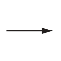
 | Perspective symbols: These symbols help in understanding the drawing's viewpoint, showing how various elements relate in three dimensions. |
Understanding Construction Drawings
Construction drawings are a visual representation of what needs to be built, encompassing a wealth of information conveyed through various symbols, lines and notations. To effectively bring a design from paper to reality, it's crucial for professionals in the field to master the art of understanding these drawings.
The Different Layers of Construction Drawings
Construction drawings are typically a set of comprehensive diagrams that include floor plans, elevations, sections and detail drawings, each providing a different perspective or detail level of the building.
Floor Plans
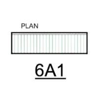
These are viewed from above, showing the layout of rooms, walls, doors, windows and other features at a particular level of a building.
Elevations
These drawings provide a vertical view of the building, showing the exterior or sometimes the interior walls. They offer details about the height, materials and features of the design.
Sections
Section drawings are cut-through views that show how the various components of the building fit together. They can reveal the construction techniques and materials specified.
Detail Drawings
These drawings provide close-up views of specific parts of the building, offering a more in-depth understanding of the construction techniques to be used.
How to Read a Legend
A legend on construction drawings acts as a comprehensive dictionary, detailing what each symbol, abbreviation or acronym featured in the drawing set means. This feature ensures that anyone reviewing the drawings can understand the information presented, regardless of their prior familiarity with specific symbols.
Often positioned as the first sheet in a drawing set, the legend serves as a central reference that the user encounters first. This facilitates a thorough understanding of the symbols and notations used throughout the drawings.
Keynotes and Schedules in Construction Drawings
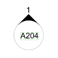
Keynotes are annotations within construction drawings that offer specific information about various elements depicted in the drawings. They link detailed explanatory notes to particular points or components within the drawings, enabling a deeper understanding without cluttering the visual representation.
Rather than embedding extensive descriptions within the drawing, a simple code can reference detailed information located elsewhere, thus ensuring clarity and consistency across the project documentation.
Schedules are comprehensive lists or tables within construction documents that detail various elements and components used in a project. They provide specific information such as sizes, materials, manufacturers, finishes and locations for items like doors, windows, fixtures and equipment. Schedules are essential for procurement, installation and ensuring that every component meets the specified requirements. They offer a consolidated view of certain elements to facilitate easy reference and verification throughout the construction process.
The Role of CAD and BIM with Construction Drawing Symbols
Computer-Aided Design (CAD) and Building Information Modeling (BIM) has revolutionized how construction drawings and symbols are used and interpreted throughout the architecture, engineering and construction industry. These technologies have significantly enhanced the representation and style of symbols, bringing a new level of precision and interactivity to construction documentation.
CAD: Enhancing Precision and Consistency
CAD software offers extensive libraries of standardized symbols, which ensure consistency across different drawings and projects. This standardization aids in maintaining clarity and reduces the risk of misinterpretation. CAD allows for the customization of symbols to suit specific project needs, adding detail and making them more informative. Furthermore, CAD streamlines the process of updating symbols across multiple drawings; changes made in one instance can be automatically reflected across all relevant documents, ensuring uniformity of project materials.
BIM: Elevating Symbols to 3D Models
In BIM, symbols go beyond mere graphical representations; they are imbued with data about the elements they represent, such as a door symbol containing information about its material, manufacturer, cost and more. Symbols in BIM can adapt to their context within the model, showing varying levels of detail depending on the viewing scale or the specific drawing extraction. BIM's 3D models allow users to interact with symbols in a spatial context, offering a comprehensive understanding of how various elements interact within a building's design.
The integration of CAD and BIM has not only transformed the visual representation and accuracy of symbols but also enhanced the collaboration among stakeholders. With the ability to access, review, and update symbols and their associated data in real-time, project development becomes a more integrated process. The standardization offered by CAD and BIM ensures that symbols and models can be shared across different platforms and software, improving communication and coordination among the various disciplines involved in a project.
The Language Behind Construction
Being able to interpret construction drawing symbols is not only about technical knowledge; it embodies the collaborative nature of construction. These symbols provide a foundation for mutual understanding, enabling professionals across various disciplines and trades to translate abstract concepts into concrete realities. As the industry continues to evolve, the ability to decipher these symbols continues to remain essential and is a critical part of project execution.
Was this article helpful?
Scroll less, learn more about construction.
Subscribe to The Blueprint, Procore’s construction newsletter, to get content from industry experts delivered straight to your inbox.
By clicking this button, you agree to our Privacy Notice and Terms of Service.
Categories:
Written by
Daniel Kavanagh
Solution Specialist, Industry Compliance | Procore Technologies
15 articles
Daniel Kavanagh is a Senior Strategic Product Consultant at Procore, based in Dublin, Ireland. Daniel is a results-oriented project manager with a passion for building relationships and exceeding client and management expectations, with career experience in project management, systems implementation, technical design and architectural finishes. Daniel has been a member of the construction industry since 2014, and graduated from the Carlow Institute of technology.
View profileTaylor Riso
Contributing Writer
95 articles
Taylor Riso is a marketing professional with more than 10 years of experience in the construction industry. Skilled in content development and marketing strategies, she leverages her diverse experience to help professionals in the built environment. She currently resides in Portland, Oregon.
View profileExplore more helpful resources

Why do most construction strategies fail (and how to fix them)?
In this episode of The Power of Construction, hosts Sasha Reed and Brett King sit down with Helen Gawor to challenge construction’s approach to strategy. Helen reveals why most strategies...

What Happens When Data Drives the Business?
Construction has long been seen as a low-margin industry. But what if the real problem isn’t the margins—it’s how decisions get made? In episode 17 of The Power of Construction,...

Preconstruction Partnerships: How Safety Pros Can Collaborate with Estimating & Proposal Teams
Construction leaders and safety professionals are developing a strong understanding of how safety programs positively impact project outcomes. When safety is woven into every aspect of operations from pre-construction to...

Types of Construction Specifications: Understanding the Difference
On a construction project, the specification book, often referred to as the “spec book,” typically contains detailed descriptions of the materials, products, systems and workmanship required. The design team —...
Free Tools
Calculators
Use our calculators to estimate the cost of construction materials for your next project.
Templates
Find a template to help you with your construction project tasks.
Material Price Tracker
Get the latest U.S. retail prices and view historical trends for common building materials.
Glossary
Explore key terms and phrases used in the industry.