
Construction Drawings: Picturing Project Success


Last Updated Jul 25, 2025
Mary Carroll-Coelho
Product Operations
12 articles
Mary Carroll-Coelho is a Product Operations Manager at Procore. A licensed Architect, Mary previously worked for KieranTimberlake, an architecture firm in Philadelphia, in construction and product operations at WeWork, and Director of Customer Success at Willow. She holds a Master of Architecture from the University of Pennsylvania. Outside of work, she volunteers as a mentor in the Spark program.
Kacie Goff
Contributing Writer
97 articles
Kacie Goff is a construction writer who grew up in a construction family — her dad owned a concrete company. Over the last decade, she’s blended that experience with her writing expertise to create content for the Construction Progress Coalition, Newsweek, CNET, and others. She founded and runs her own agency, Jot Content, from her home in Ventura, California.

Every construction project — whether it be a kitchen renovation or a new highway overpass — relies on a set of comprehensive drawings to communicate what should be constructed.
For the uninitiated, drawings can be disorienting to look at. They mostly resemble a 2-dimensional building, but only in black and white. They include various symbols, annotations, multiple line types and arrows everywhere. There are also many versions of drawings that offer different levels of detail, different information (such as an electrical drawing for electricians) and different perspectives.
In this article, we will demystify construction drawings, describe the various types of drawings that make up the drawing set, and explain their role in construction projects.
Deep dive: Deciphering Construction Drawing Symbols
Table of contents
Drawings as Part of the Contract
Drawings are much more complex than a set of sketches that tell contractors what to build — they represent a comprehensive and definitive collection of designs that are part of the contract documents — meaning, contractors are legally bound to construct what’s in the drawings.
The extent of the drawing set varies with the project's scope, potentially encompassing a voluminous number of sheets (the term for a page within the drawing set). Drawing sets constitute a fundamental component of the preliminary information presented to stakeholders, instrumental in informing and influencing the construction outcome.
To be clear, drawings don’t tell the general contractor (GC) and their various teams how to build — instead, the drawings provide the criteria for the building, factoring in everything from the owner’s preferences to applicable codes and standards. Within the drawings set, the architects and engineers communicate the intent of the design to contractors, whose job it is to then execute according to that intent.
The Phases of a Drawing Set
The drawing set is the collection of the many different types and categories of drawings for a construction project, serving as the primary tool for communication among everyone involved in the construction process, such as architects, engineers, contractors, and subcontractors. The drawing set needs to communicate everything from overall site plans all the way down to which bolts get used. That’s why drawing sets are usually at least dozens of pages long, and can range up to 1,000 pages or more.
Drawing sets aren’t created overnight. Larger projects can take years of work, coordination, owner approval, and even peer review. Because this process is so lengthy, it has become standard practice to phase out drawing sets based on the amount of detail, ensuring that architects and owners are on the same page before spending time on wasted efforts.
The AEC (architect, Engineering, and Construction) industry deploys generally accepted common phases for breaking up the drawings:
| Drawing Set Phase | Description | Level of Detail |
|---|---|---|
| Schematic Design (SD) | This phase focuses on conceptualizing the project and exploring design options. | Drawings are typically conceptual in nature, providing an overall layout, massing diagrams, basic floor plans, and elevations. They may also include rough sketches and diagrams to convey design intent. |
| Design Development (DD) | This phase further refines the design based on feedback from the owner and stakeholders. The 100% DD set is often considered a pricing set. The owner will use this drawing set to gauge the current cost of the project. | Drawings become more detailed compared to SD. Floor plans are refined, and more detailed elevations, sections, and site plans are developed. Material selections and basic structural systems may also start to be specified. |
| Construction Documents (CD) | This phase involves the creation of detailed drawings and specifications necessary for construction. This phase is generally the longest and has the most “check points” or percentage breaks. On larger projects, it’s common to have a 50% CD set, a 75% CD set, a 95% CD set, and 100% CD set. | Drawings in this phase are highly detailed and comprehensive. They include precise dimensions, annotations, and specifications for all aspects of the project including architectural, structural, mechanical, electrical, plumbing, and any other pertinent systems. These drawings are intended to provide contractors with all the information they need to construct the project accurately. |
| Permit Set | The goal of this drawing set is squarely to secure a building permit from the local AHJ (or Authority Having Jurisdiction). This is a governing body, often a city municipality, that controls the regulatory review and approval process. | A permit set encompasses detailed architectural, structural, MEP, site, and landscape drawings, along with supporting documentation to demonstrate compliance with relevant codes and regulations. This drawing set is less comprehensive and generally omits the vast number of details required for construction. The goal of this set is threefold: obtaining regulatory approval, legal compliance, and risk mitigation. |
| Bid Set | This phase involves selecting a contractor through a bidding process or negotiation.Depending on the scale of the project, you may see that the 100% Construction Documents set is used at the Bid Set, they are one and the same. | The drawings and specifications are used to solicit bids from contractors. They need to be detailed enough to accurately estimate the cost of construction, but they may still be subject to minor revisions based on contractor feedback. |
| For Construction Set | The "For Construction Set" refers to the finalized set of detailed plans and specifications that are prepared for use during the actual construction process. | A For Construction set that incorporates the technical specifications, dimensions, materials, and building methods that contractors require to accurately carry out the work. |
Categorizing Drawing Sets
Because of the amount of detail required in drawings for construction projects, there are many different categories of drawings. For instance, an electrician will refer to the electrical drawings. But drawings are categorized even within the electrical drawings to show different visual perspectives, often referred to as plans.
Because there are so many different types of drawings, we have simplified the categories of drawings into two different sets, categorizing by specialty, trade and by the perspective/point of view of the drawing.
By Specialty
Within the drawing set, stakeholders can find drawings guiding all of the work that needs to be completed on the site. Because different projects have different requirements, the types of drawings included in the set vary. For example, one project might include landscape drawings. Another might leave it out because existing landscaping will be left unchanged or landscaping will be considered later.
Generally, though, construction drawing sets include sections of drawings to guide the following areas.
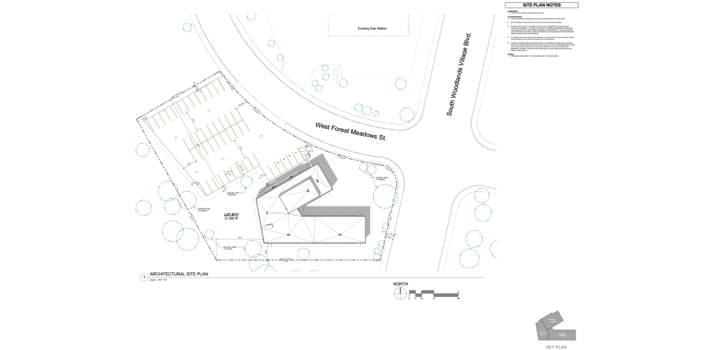
- Site plans: This portion of the set lays out the purpose of the project on the site. It maps out everything that will be built. The site plans provide a zoomed-out, big-picture view of the project.
- Civil drawings: This part of the drawing set details any in-ground work that needs to happen (i.e., earthwork), like where to dig for and install sewer lines or how to attach to utilities. Civil drawings also provide technical details about the site like the grading.
- Structural drawings: As the name suggests, these drawings detail the structural elements of the project. These drawings outline what needs to be put where to ensure that anything that gets built is structurally stable.
- Architectural drawings: These drawings include everything from floor plans and section drawings — which might show where to put a window, for example — to more granular details that communicate the intent of the design and the desired outcome. The architectural drawing portion of the set also includes elevation drawings, which generally show how the building will look to someone standing outside looking at it, along with vertical cross-sections.
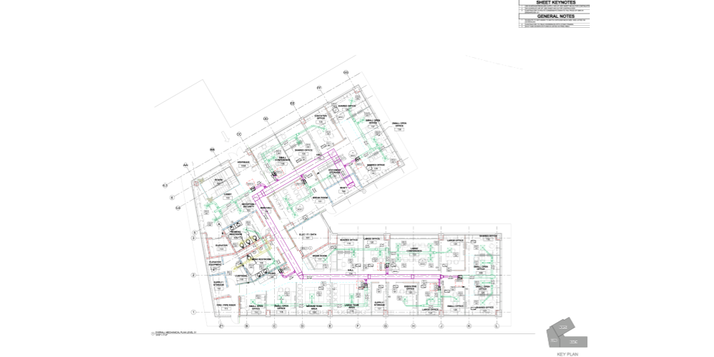
- Mechanical, electrical, and plumbing (MEP) drawings: Each of these disciplines gets its own set of drawings detailing what work needs to be done where. The electrical drawings show the electrical contractor where to put wiring, outlets and fixtures, for example. Similarly, the mechanical drawings might outline the schematics for the building’s HVAC system. The MEP drawings make specifications so that what gets installed is compliant with relevant codes and regulations.
- Fire protection drawings: These detail where fire alarms should go and lay out suppression systems, like sprinklers.
- More granular drawing sections: Most drawing sets include other sections based on the project’s requirements. Some might include a set of audio-visual and information technology (AV/IT) drawings or interior design drawings (when those are part of the contract). The project might include a set of finish drawings, for example, a hotel project that specifies what finishes are required based on the room type. Construction drawings get as detailed as the project requires. They might even include references to things the client is providing, like their own refrigerators.
By Perspective
Plans
Plans are detailed drawings from a specific perspective of a building or structure — for instance, a floor plan will be a top-down (aerial) perspective. These drawings are scaled to show specific features — such as rooms, spaces, and physical features. Plans for a building with multiple levels will have a set of plans for each level.
A few different types of plans are:
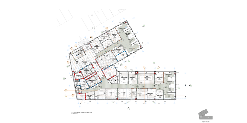
- Floor plans: Floor plans show the layout of each floor within a building, revealing the placement of walls, doors, windows, stairs, and other fixtures. Floor plans also indicate room sizes and functions, locations for plumbing and electrical systems, and include notes for construction details.
- Site plans: Site plans provide an overview of the entire construction site, including the building footprint, access points, parking, landscaping, and the relationship to surrounding structures and features. These plans are crucial for understanding how a building sits within its environment.
- Roof plans: Roof plans detail the design and complexity of the roof structure, including slopes, ridges, valleys, and any roof features such as vents, skylights, or chimneys.
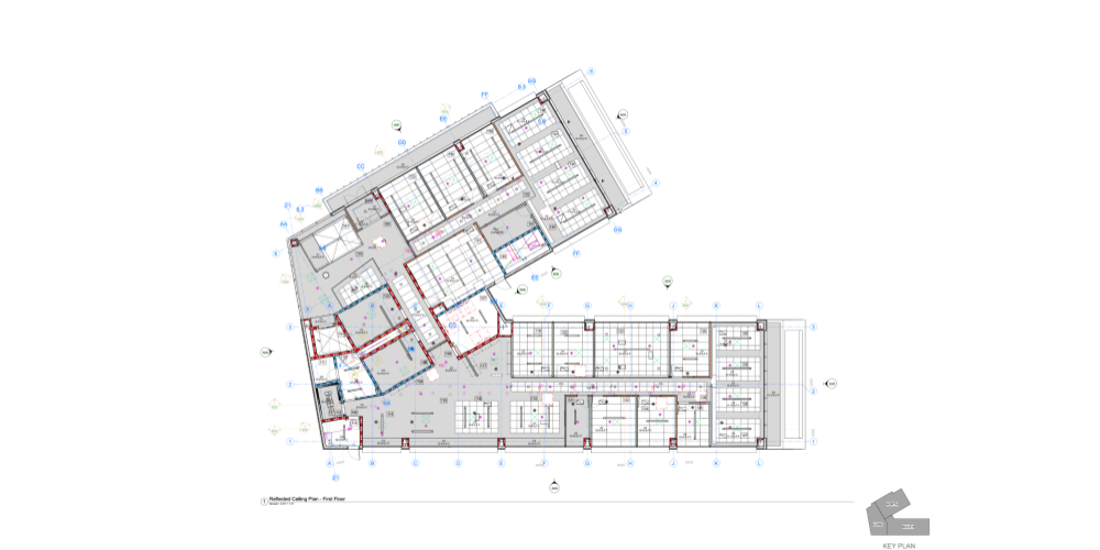
- Reflected ceiling plans (RCPs): RCPs are similar to floor plans but are focused on the ceiling. They show the layout of ceiling elements, including lighting fixtures, HVAC components, and decorative elements, as seen in a mirror reflection if the floor were transparent.
Sections
Sections are drawings that depict a vertical cut through a structure, providing a clear understanding of the vertical relationships between different parts of the building. They are used to show the internal structure and components of a building or object that are not visible in plans or elevations.
Here are key points about sections in construction drawings:
- Building sections: Building sections show a cut through the main body of the building, revealing the construction from the foundation through to the roof, illustrating the different levels of the building.
- Wall sections: Wall sections magnify the details on walls in a building project, highlighting the layers of materials such as insulation, drywall and finishes.
- Detail sections: Detail Sections are enlarged sections that show even greater detail — such as different materials and components. They might depict particular junctions, connections, or transitional areas that require careful consideration during construction.
- Cross sections: Similar to building sections, cross sections specifically refer to cuts that are made perpendicular to the longitudinal axis of an element or space.
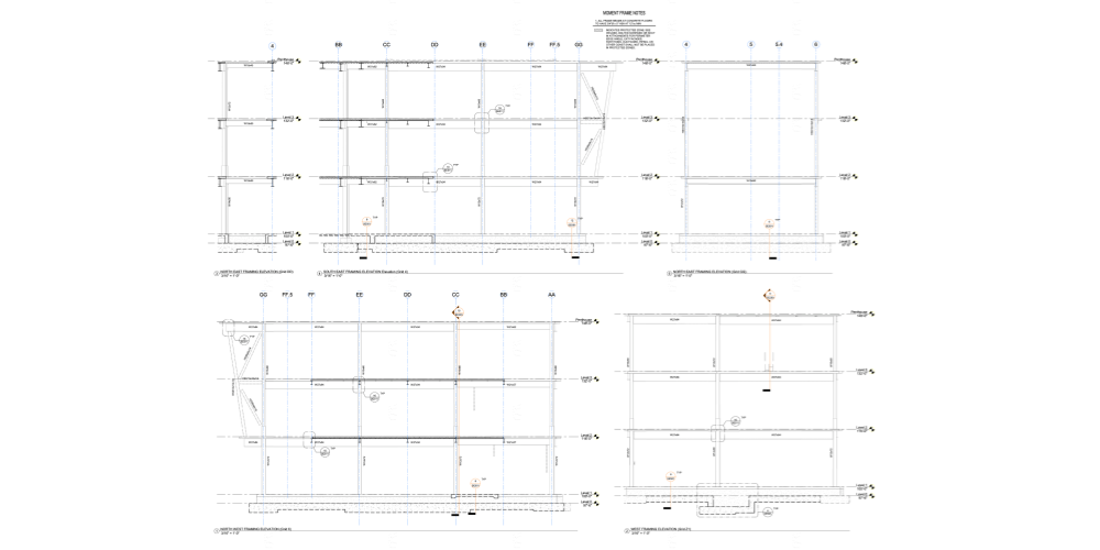
Elevation
Elevation drawings depict a building – or, a segment of it – from a vertical perspective, providing a head-on view of a building's exterior or an interior wall. It's analogous to standing right in front of a building and gazing directly toward it. A few elevation drawing types are:
- Elevation: A depiction of the exterior of a building or structure.
- Interior Elevation: An illustration of an interior wall or space within a building.
- Elevation Call Out: A reference to a more detailed elevation drawing, typically indicated within a larger drawing or plan.
- Elevation Detail: A closer, more detailed look at a particular aspect of the elevation, often used to convey complex construction details.
How Drawings Are Organized
The drawing set typically gets organized with the most zoomed-out view (i.e., site plans) first. Then, they move bottom up. The civil drawings detail what needs to happen underground, for example, while the structural plans outline the foundation.
That said, clients might have a specific order in which they want to receive the drawings. And the drawings usually follow the order of the spec book (i.e., the project’s specifications). As a result, in the same way that what’s included in a construction drawing set varies from project to project, the organization of those drawings can change.
Still, stakeholders need a way to find the information that’s relevant to them. Most GCs and trades professionals only receive the drawings pertinent to the work they need to do.
Owners, investors, and others might need to find the information they want in the drawing set, though. For organization purposes, construction drawings usually label the sections. For example, all architectural drawings might be labeled as the “A” set, with numbers following the “A” to indicate the specific drawing (e.g., “A-101”).
Common organizational labels for construction drawings include:
- A: architectural
- S: structural
- M: mechanical
- E: electrical
- P: plumbing
- SP: sprinklers
These labels, often referred to as sheet numbers, help clarify the construction drawings for authority-having jurisdictions (AHDs), like cities and counties that need to review plans before greenlighting a project or issuing permits. For a more comprehensive list of labels, follow this guide from the National CAD Standard.
Stay updated on what’s happening in construction.
Subscribe to Blueprint, Procore’s free construction newsletter, to get content from industry experts delivered straight to your inbox.

What’s included in drawings?
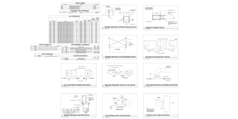
Drawings need to provide an extremely granular level of detail, each might be paired with a schedule.
This isn’t a schedule in terms of a timetable. Instead, it’s a spreadsheet of details that get “scheduled out.” The architect usually determines a coding system for windows and doors (e.g., “door type A,” “door type B” ), for example. The drawing will show that “door type A” should go in a specific place. Referencing the attached schedule reveals the dimensions of the door, its material, and other necessary details.
The schedule isn’t the only thing supplementing the drawing, either. The spec book often plays a role, too.
For example, the drawing might include a detail of an area, including bolts, flanges, structural welding, and something called “coating type A.” The attached schedule might explain what types of bolts and flanges are required, plus other details that can be called out simply. The drawing could then specifically note to reference the spec book for “coating type A.” The specs could then call out that the coating needs to include three layers of marine-grade coating and be galvanized if it’s used underground.
Ultimately, between the construction drawings, the schedules attached to the drawings, and the spec book, every stakeholder on the project should have complete clarity around what the building requires.
Technology Drives Change in Drawings
Clear construction drawings lay a firm foundation for the GC, subcontractors and other parties to work. Because construction drawings can quickly become extensive, it’s no surprise that architects and engineers have adopted technology to help. Computer Aided Design (CAD), for example, allows them to develop drawings more quickly while also eliminating some of the human errors that came with hand-drawing plans.
Some people might be surprised to learn that the construction drawings included in a contract are still presented in 2D, even in 2024. This is because tracking changes in three dimensions within those models is still difficult, though. Changes to the project after the contract is awarded can quickly result in additional cost to the owner, something owners want to avoid. Slicing the 3D models into 2D drawings gives everyone clear, direct visibility into the parts of the project for which they’re responsible.
While most projects still move forward with 2D drawings, many architects and engineers model the building in 3D with building information modeling (BIM), and then slice it into those 2D sections. 3D building information modeling delivers gains like easier visualization, virtual walkthrough functionality, and clash detection. In fact, in the European Union (EU), most projects already require building models with a specific level of detail. Though there are still a few kinks that need to be worked out, it’s safe to say that in the future, 3D modeled drawings will become the standard.
Was this article helpful?
Scroll less, learn more about construction.
Subscribe to The Blueprint, Procore’s construction newsletter, to get content from industry experts delivered straight to your inbox.
By clicking this button, you agree to our Privacy Notice and Terms of Service.
Categories:
Written by
Mary Carroll-Coelho
Product Operations
12 articles
Mary Carroll-Coelho is a Product Operations Manager at Procore. A licensed Architect, Mary previously worked for KieranTimberlake, an architecture firm in Philadelphia, in construction and product operations at WeWork, and Director of Customer Success at Willow. She holds a Master of Architecture from the University of Pennsylvania. Outside of work, she volunteers as a mentor in the Spark program.
View profileKacie Goff
Contributing Writer | Procore Technologies
97 articles
Kacie Goff is a construction writer who grew up in a construction family — her dad owned a concrete company. Over the last decade, she’s blended that experience with her writing expertise to create content for the Construction Progress Coalition, Newsweek, CNET, and others. She founded and runs her own agency, Jot Content, from her home in Ventura, California.
View profileExplore more helpful resources

The role of an owner’s project manager — and their collaboration with construction managers
Many people help make a construction project happen, and roles often overlap, but the owner’s project manager (OPM) is a layer of management that explicitly looks out for the project...

How leading retailers optimize capital portfolio execution
Most retailers are managing fast-moving capital portfolios with a key problem: Project data lives in their GC’s systems and not their own. Without owning that data, they’re perpetually reactive on...

Unlocking success with capital portfolio management: A guide for private owners
For capital project leaders, overseeing multiple active developments is a complex balancing act of risk, compliance, and careful financial management. And for organizations that operate without an in-house general contractor...

How detailed change logs help GCs resolve disputes faster
Most construction professionals have heard something similar: “That’s reasonably inferred and it should have been in the contract.” Between scope creep, change orders, and all of the other uncertainties that...
Free Tools
Calculators
Use our calculators to estimate the cost of construction materials for your next project.
Templates
Find a template to help you with your construction project tasks.
Material Price Tracker
Get the latest U.S. retail prices and view historical trends for common building materials.
Glossary
Explore key terms and phrases used in the industry.